Wednesday, April 13, 2011

CNC Line

Its a line of CNC machine that organized to make a continuous CNC product from one machine to the others.
Sample of CNC Line :

Product Bracket
Operation 1 : Milling
Operation 2 : Drilling & Chamfering
Operation 3 : Turning
Operation 4 : Back Facing & Chamfering.

The CNC Line model is consist of 4 machine, that the position is sequenced by its operation.

start   OP 1   ->   OP 2   ->   OP3  ->  OP 4     finish

Hope with that sample will make you understand.


Thursday, March 10, 2011

Tool Geometry Offset and Tool Wear Offset

Tool geometry offset and tool wear offset are possible to divide the tool offset to the tool geometry offset for compensating the tool shape or tool mounting position and the tool wear offset for compensating the tool nose wear. The tool geometry offset value and tool wear offset value can be set individually. When these values are not distinguished from each other, the total of the values is set as the tool offset value.
NOTE : Tool geometry offset and tool wear offset are optioned.

Let me show you if tool geometry offset and tool wear offset are distinguished from each other (picture left) and if they are not (picture right).

Tool Ofsett in CNC program


Usually, several tools are used for machining one workpiece. The tools have different tool length. It is very troublesome to change the program in accordance with the tools. Therefore, the length of each tool used should be measured in advance.
By setting the difference between the length of the standard tool and the length of each tool in the CNC machining can be performed without altering the program even when the tool is changed.
This function is called tool offset.

Tuesday, November 9, 2010

Program CNC configuration in CNC machine (part 2)

Reffer to the last post in program CNC configuration part 1 here
We will continue to program section configuration, a program section consist of several blocks. A program section starts with a program number and end with a program end code.

Program section configuration                                     Program section
Program number                                                              O0001;
Block 1                                                                           N1 G91 G00 X120.0 Y80.0;
Block 2                                                                           N2 G43 Z-32.0 H01;
Disable execution block                                                   / N3 G00 Z-200.0;
:

:
Block n                                                                           Nn Z0.0;
Program end                                                                   M30;

A block contains information that necessary for machining, such as a move command or coolant on/off command. Adding a slash ( / ) at the start of a block will disable the execution of some blocks.
A program number consisting of address O followed by a four–digit number is assigned to each program at the beginning registered in memory to identify the program.
In ISO code, the colon ( : ) can be used instead of O.
When no program number is specified at the start of a program, the sequence number (N....) at the start of the program is regarded as its program number. If a five–digit sequence number is used, the lower four digits are registered as a program number. If the lower four digits are all 0, the program number registered immediately before added to 1 is registered as a program number. Note, however, that N0 cannot be used
for a program number.
If there is no program number or sequence number at the start of a program, a program number must be specified using the MDI panel when the program is stored in memory

Program CNC configuration in CNC machine (part 1)

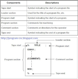
There are two types of program in cnc programming, there are main program and subprogram. Normally the CNC operates according to the main program. However, when a command calling a subprogram is encountered in the main program, control is passed to the subprogram. When a command specifiying a return to the main program is ecountered in a subprogram, control is returned to the main program.

The CNC memory can hold up to 400 main programs and subprograms.  A main program can be selected from the stored main programs to oprate the machine.
Usually the program consist of the followong component.

Thursday, November 4, 2010

List of G Code in CNC programming

This is the list of G Code in CNC programming, also there is a group number and the function of the G code.


1. The modal G codes are placed in the states described below.

(1) The modal G codes are placed in the states marked with as indicated in Table 3.
(2) G20 and G21 remain unchanged when the clear state is set at power–up or reset.
(3) Which status G22 or G23 at power on is set by parameter G23 (No. 3402#7). However, G22 and G23 remain unchanged when the clear state is set at reset.
(4) The user can select G00 or G01 by setting bit 0 (G01) of parameter No. 3402.
(5) The user can select G90 or G91 by setting bit 3 (G91) of parameter No. 3402.
(6) The user can select G17, G18, or G19 by setting bit 1 (parameterG18) and bit 2 (parameter G19) of parameter No. 3402.

2.G codes other than G10 and G11 are one–shot G codes.

3.When a G code not listed in the G code list is specified, or a G code that has no corresponding option is specified, P/S alarm No. 010 is output.

4.Multiple G codes can be specified in the same block if each G code belongs to a different group. If multiple G codes that belong to the same group are specified in the same block, only the last G code specified is valid.

5.If a G code belonging to group 01 is specified in a canned cycle, the canned cycle is cancelled. This means that the same state set by specifying G80 is set. Note that the G codes in group 01 are not affected by a G code specifying a canned cycle.

6.G codes are indicated by group.

7.The group of G60 is switched according to the setting of the MDL bit (bit 0 of parameter 5431). (When the MDL bit is set to 0, the 00 group is selected. When the MDL bit is set to 1, the 01 group is selected.)

G Code in CNC Programming

G-codes are also called preparatory codes, and are any word in a CNC program that begins with the letter "G". Generally it is a code telling the machine tool what type of action to perform, such as:
- Rapid move
- Controlled feed move in a straight line or arc
- Series of controlled feed moves that would result in a hole being bored, a workpiece cut (routed) to a specific dimension, or a decorative profile shape added to the edge of a workpiece.
- set tool information such as offset.


A number following address G determines the meaning of the command for the concerned block.
G codes are divided into the following two types.
1. One-shot G code
    The G code is effective only in block in which it is specified
    Example :
      N011 G00 X0 Y0 M5; 
        N012 G49 Z250.0 T15 M6;
        N013 G43 Z0 H15;
        N014 S20 M3;
        N015 G99 G82 X550.0 Y–450.0 Z–130.0 R–97.0 P300 F70;
      The G82 also known as drilling cycle is use only one shot.

2. Modal G code
    The G code is effective until another G code of the same group is specified
    Example :
      N010 G01 X0.0 Y0.0 F500 ;
        N020 Z50.0;
        N030 X20.0;
        N040 X25.0 Y15.0;
        N050 GO X0.0 Y0.0:
  
       The G01 is effective in range N010 - N040, until there is another G comand or program end.